LBO, SBO and SWZ for a `tcgen05` tile
Following up on my last post on Grouped GEMMs, where I used Ampere-era MMA instructions for GEMM, I moved on to understanding tcgen05 on Blackwell. During that, one aspect I found myself spending a lot of time with was the SBO/LBO/SWZ shared-memory addressing parameters and imagined it would be worthwhile just sharing some thoughts here. This write up is more about what I gathered on SBO/LBO/MBO/SWZ while using the tcgen05.mma instruction and some simple "aha" moments along the way.
I would highly recommend giving this great write up by Thien Tran a read to understand the tcgen05 in detail. It does a great job of breaking down these addressing parameters into a much less complex form than they are on the Nvidia docs and that proved really helpful for my understanding. Also, thanks to the back and forth with Grok 4.6 and GPT 5.6 Sol, understanding these didn't take forever.
Most of the following revolves around the tcgen05.mma.cta_group::1.kind::f16 instruction (since this is a continuation of the ampere-mma bf16 GEMM I covered in the last write up).
constexpr int BM = 128;
constexpr int BN = 128;
constexpr int BK = 32;
constexpr int WARPS_PER_BLOCK = 4;

__shared__ __align__(512)  half A_shared[2][BM][BK];
__shared__ __align__(1024) half B_shared[2][BK][BN];
This code excerpt here is to (a) Reiterate the tile sizes operated on by a CTA and (b) Highlight the alignment I used for A and B in the shared memory. I go into the details of this requirement in a later section below. So, till then, please bear with me and accept that these 512-byte and 1024-byte alignments for A and B respectively are required as a consequence of how they are swizzled in the shared memory and what is the base offsetof where they start.
The MMA/TMEM path in this kernel is still incomplete; this post just covers the shared-memory layouts and descriptors.
1. What is a core matrix and why the 8 x 16B size?
This is perhaps on me that I never really spent a lot of time understanding the intrinsics of Hopper (and WGMMA), so this shared-memory organization was new to me. NVIDIA's Shared Memory Layout and Swizzling section was particularly helpful but it's a bit too much. So, if you need to refer to something, I would recommend focusing on the discussion around the K-major layout as that is what I focus on below.
Given
BM=128,BN=128, andBK=32, themmainstruction I used ism128n128k16. This consumesA[128 × 16]andB[16 × 128]and updatesD[128 × 128].
Now, if you are wondering why 128 x 16 and not 128 x 32 since BK = 32 - well, that's how the FP16 MMA instruction works. It supports K=16 in one call and thus, we need two calls to m128n128k16. The first covers K[0:16] and the other covers K[16:32], both accumulating over the same D[128 x 128].
So, that covers how much data each MMA call consumes. Accordingly, the next step was to understand how the data needs to be arranged in the shared memory for tcgen05.mma.
Nvidia describes these layouts in 16-byte cells, laid out along the K-dimension for a K-major layout. These cells can be stored with no swizzle, or using SW32, SW64, or SW128. Essentially, the storage in shared memory and the Swizzle mode needs to be in sync or tcgen05.mma just ends up reading garbage. This figure below ties the swizzle modes with the number of 16-byte cells along the K-dimension. This will be useful when understanding how the mma accesses data from the shared memory
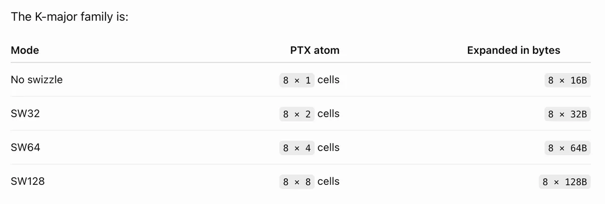
Along with the K-major layout, Nvidia also supports MN-major layout which is used by B. For a K-major FP16 A operand, each cell (of 16 Bytes) contains eight consecutive values along K. Here, since I have BK=32, every 64-byte row contains four such cells and laid out as follows (code to follow below) -
             q0             q1             q2             q3
A row m   K[0:8]         K[8:16]        K[16:24]       K[24:32]
             16 B           16 B            16 B            16 B
Logically, one 16-byte cell is taken from each of eight consecutive M rows. I use the term core matrix from Modular’s blog for this 8 × 16B group.
A core matrix represents this
8 × 8FP16 block, i.e. a segment of8 x 16Bblock.
The left panel in the figure below shows the organization of one core matrix. The middle parts shows the two core matrices, consumed by one K=16 MMA call and the right shows the four core matrices that are present when BK=32 - these are consumed across two MMA calls
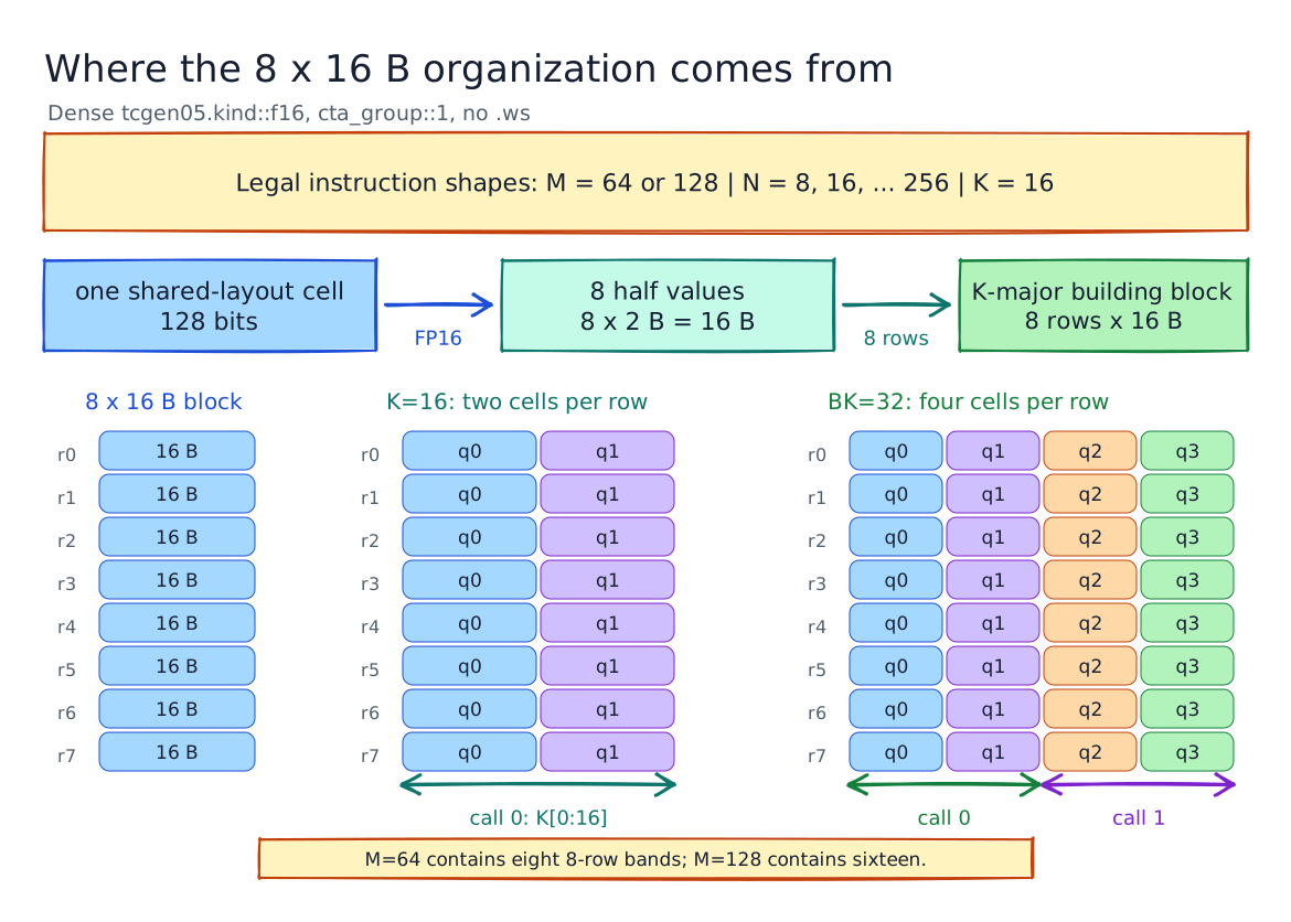
The rightmost panel is an 8 x 4 logical grid of 16-byte cells with q0-q3 presented in the logical order without the SW64 swizzle. In the physical layout of the K-major A_shared array, the complete 64-byte row is stored before the next row begins.
2. How A_shared is organized in the shared memory
Once I was able to get past the fundamentals of core matrices and the 8 × 16B shared-memory layout unit, the next step was connecting that with the data loaded into A_shared. The organization of A_shared follows the cooperative tile-loading pattern in Siboehm's Matmul Kernel Worklog: each thread loads one 16-byte chunk per loop iteration, and consecutive threads generate coalesced global-memory requests. Since BK=32, four consecutive threads cover one complete A row.
This code block shows exactly how threads map to shared-memory destinations. If you are not familiar with __pipeline_memcpy_async, it is just a fancy way of saying “asynchronously copy data from global memory to shared memory.” Each call here copies 16 bytes.
constexpr int VEC_ELEMS = 16 / sizeof(half);       // 8
constexpr int chunks_per_row_A = BK / VEC_ELEMS;  // 4
constexpr int num_rows_per_iteration_A =
    (WARPS_PER_BLOCK * 32) / chunks_per_row_A;     // 32
constexpr int num_rd_iterations_per_block_A =
    BM / num_rows_per_iteration_A;                 // 4

const int thread_col_A =
    (threadIdx.x % chunks_per_row_A) * VEC_ELEMS;

for (int i = 0; i < num_rd_iterations_per_block_A; i++) {
    int shared_next_row_a = threadIdx.x / chunks_per_row_A
                          + i * num_rows_per_iteration_A;
    int global_next_row_a = global_row_offset_A
                          + i * num_rows_per_iteration_A;

    __pipeline_memcpy_async(
        &A_shared[stage][shared_next_row_a][thread_col_A],
        &A[global_next_row_a * K + thread_col_A],
        16
    );
}
For one read iteration i, relative to the beginning of A_shared[stage], threadIdx.x writes to:
m = floor(threadIdx.x / 4) + 32*i
q = threadIdx.x mod 4

byte_current_A(m,q) = 64*m + 16*q
where each loop iteration uses groups of four consecutive threads to write four adjacent 16-byte chunks of each A row, covering 32 rows per iteration and all 128 rows across four iterations.
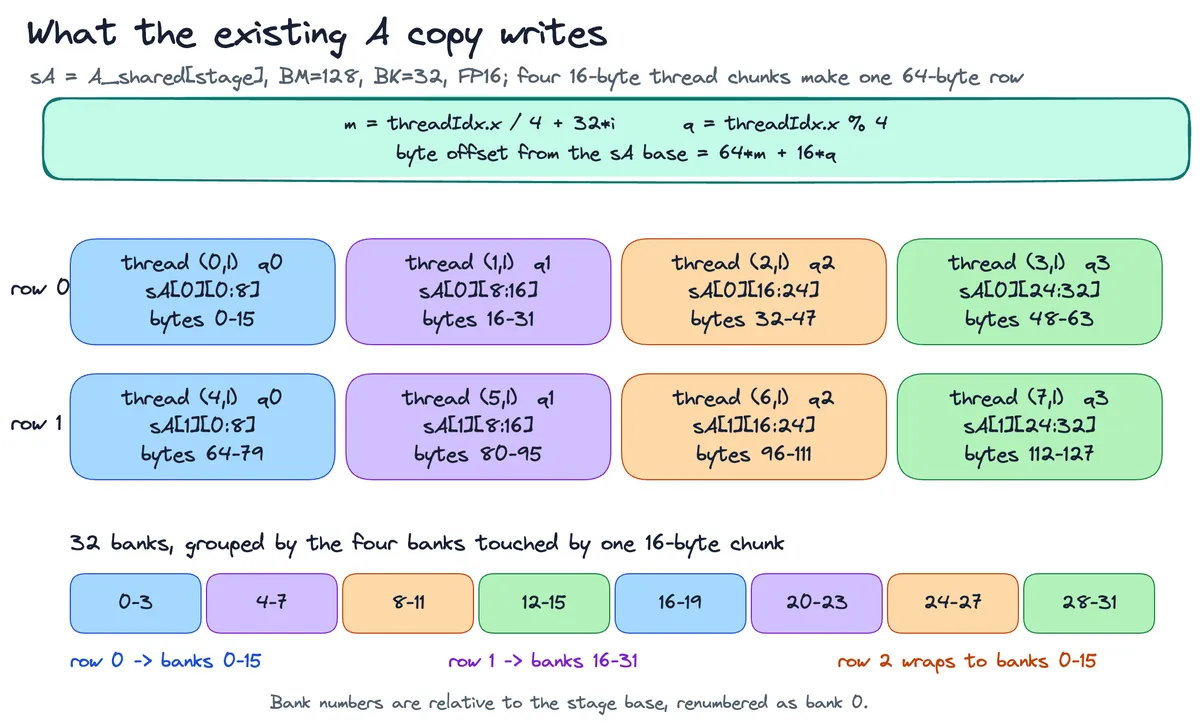
This figure shows relative to the bank where a row begins and how the four chunks land:
q0: A[m][ 0: 8] -> banks + 0.. 3
q1: A[m][ 8:16] -> banks + 4.. 7
q2: A[m][16:24] -> banks + 8..11
q3: A[m][24:32] -> banks +12..15
Accordingly, for q0, rows 0 through 7 start at bytes 0, 64, 128, 192, 256, 320, 384 and 448.
3. tcgen05.mma instruction with Swizzle, SBO, and LBO.
Let me give you a quick motivation for this section.
Based on how A is stored in the shared memory, my initial understanding was, row0 of the core matrix is at bank 0:3 in the SMEM, then row1 is at bank 16:19 (given that rows are 64-bytes apart), then naturally row2 of the core matrix, which is again 64-bytes away, should be at bank 0:3, in the next slot of the SMEM. And this is where things fell apart.
row2is actually expected atbank 4:7,row3at20:23,row4atbank 8:11, and so on. This is whereswz_col_Aalso comes in, to determine the banks shared memory uses.
So, in the following section, I have tried to breakdown all the factors that affect this ordering (and hopefully in a not too convoluted manner).
First things first, the tcgen05.mma instruction for FP16 is as follows:
tcgen05.mma.cta_group::1.kind::f16
     [d_tmem], a_desc, b_desc, idesc,
     {mask0, mask1, mask2, mask3}, enable_input_d;
Thien Tran's blog, tcgen05 for dummies, is a great introduction for anyone looking to understand tcgen05. The operands I mostly discuss in this section are a_desc and b_desc since they are the ones directly affected by SBO, LBO, MBO, and SWZ. These are 64-bit shared-memory descriptors that tell tcgen05 where A and B begin in SMEM and how their bytes are laid out there.
Let's look at a_desc first. I believe it is enough to understand how the physical shared-memory layout connects to SWZ and SBO. Major differences for b_desc are a consequence of its MN-major orientation instead of the K-major used by A - which also affects how LBO is set and used.
Together, a_desc0 and a_desc1 describe the two K=16 views of A_shared[stage]. The complete stage contains 128 rows × 32 halves, uses the K-major SW64 layout, and begins on a 512-byte boundary:
a_desc0  -> A[0:128,  0:16]
a_desc1  -> A[0:128, 16:32]
Let P be the aligned beginning of A_shared[stage] (also interchangeably used as pattern start address). The physical address of each logical 16-byte cell is:
addr(band, r, q) = P + band·SBO + r·64 + (q ^ ((r >> 1) & 3))·16

P    = beginning of the SW64 pattern
band = 0..15    eight-row group within M=128
r    = 0..7     row within that group
q    = 0..3     logical 16-byte K cell within the BK=32 row

a_desc0 selects q0 and q1
a_desc1 selects q2 and q3
P remains the start of the SW64 pattern for both MMA calls. The matrix-start field in a_desc1 is P + 32 B, selecting the second pair of logical K cells. The beauty of the next MMA call reading from just P + 32 is that it doesn't affect the MBO - you'll see why soon.
The descriptor fields map directly to the address above:
| Descriptor field | Value | Role in the address |
|---|---|---|
| matrix start | encode(P) for a_desc0; encode(P + 32) for a_desc1 |
selects q0/q1 or q2/q3 |
| SBO | 512 B, encoded field 32 |
band·SBO moves to the next eight-row group |
| SWZ | raw value 4, meaning SW64 |
defines the 64-byte row layout and the q ^ (r >> 1) & 3 permutation |
| LBO | unused; encoded field 1 |
contributes no address stride for a K-major swizzled layout; default set to 1 |
| MBO | 0 |
makes the SW64 pattern begin with the zero phase; for __align__(512) set to 0 |
Now, what is MBO or Matrix Base offset? MBO records where the swizzle pattern begins relative to its natural boundary - in units of 128 bytes.
A good way for me to understand how MBO works was to compare at how key in the addr changes when the start address is set to start at 128-byte instead of the expected 512-byte address for the SW64 pattern.
Had it not been for the patience
Grok 4.6andGPT 5.6 Solshowed with me on this, I would have still been scrambling for resources to understand the interplay betweenMBOandpattern start address.
Concretely, with MBO=0 the hardware assumes the swizzle pattern begins on its natural boundary — 256 B for SW32, 512 B for SW64, 1024 B for SW128. The XOR key begins at zero and changes every two rows:
rows 0–1 → key 0
rows 2–3 → key 1
rows 4–5 → key 2
rows 6–7 → key 3
If the pattern instead starts at shared-memory byte address 128, PTX computes:
MBO = (pattern_start_address >> 7) & 7
    = (128 >> 7) & 7
    = 1
This >>7 expresses the pattern start in 128-byte units. For SW64, the XOR key uses the lowest 2 bits:
key = ((MBO & 3) + (r >> 1)) & 3
And with MBO=1, the key shifts by 1 thereby changing the SMEM bank locations:
rows 0–1 → key 1
rows 2–3 → key 2
rows 4–5 → key 3
rows 6–7 → key 0
Aside: When I started working each of these equations out, it got a bit confusing and I found playing Q&A with an AI agent to be extremely helpful.
Similarly, SBO is straightforward for this packing. Each row occupies 64 bytes, and one K-major atom contains eight rows:
SBO = 8 rows × 64 B = 512 B

encoded SBO = 512 / 16 = 32
For K-major configuration with non-zero SWZ, LBO is a don't care for address calculation, although it's encoded as
1.
At this point, I think we have all the components to put together the Shared Memory descriptor for A. The matrix-start, LBO, and SBO address fields are encoded in 16-byte units. MBO and SWZ are separate raw three-bit fields. The make_smem_desc() helper takes care of it. Following are snippets from the code for setting the descriptors and corresponding helper variables:
constexpr uint32_t A_LBO = 16;  // 16 / 16 = encoded field 1
constexpr uint32_t A_SBO = 512;
constexpr uint32_t A_SWZ = 4;   // SW64
The SW64 key in the general case is:
key = ((P / 128) + (r >> 1)) & 3
A_shared[stage] begins on a 512-byte boundary, so:
(P / 128) & 3 = 0
This leaves:
key = (r >> 1) & 3
and therefore:
q_phys = q ^ ((r >> 1) & 3)
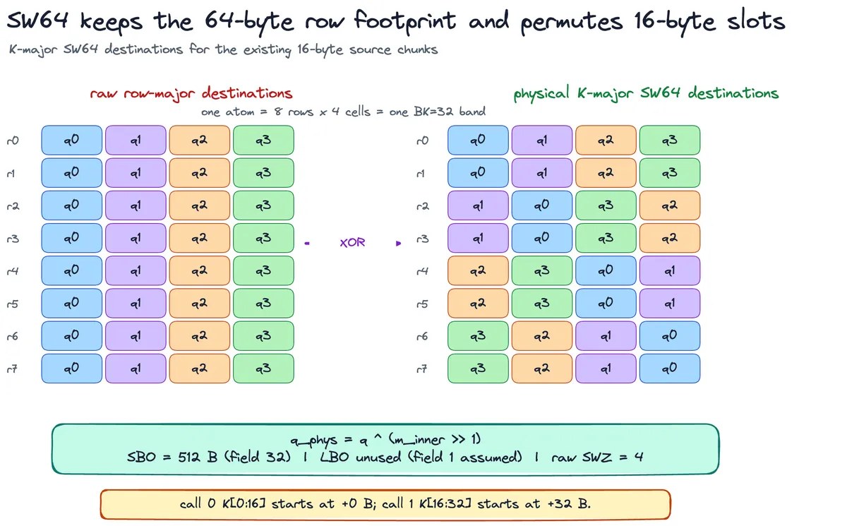
This is the physical slot used by the shared-memory store:
int slot_A = threadIdx.x % chunks_per_row_A;  // logical q0, q1, q2, or q3
int swz_col_A =
    (slot_A ^ ((shared_next_row_a >> 1) & 3)) * VEC_ELEMS;

__pipeline_memcpy_async(
    &A_shared[stage][shared_next_row_a][swz_col_A],
    &A[global_next_row_a * K + thread_col_A],
    16
);
The global-memory source remains in logical q0, q1, q2, q3 order. The destination uses swz_col_A to place each chunk in the SW64 physical order expected by a_desc.
So, for the params for A, moving to the next eight-row group requires 8 × 64 = 512 bytes. The 64-byte row layout and its XOR permutation are a consequence of SW64 itself, which also leak into the values for MBO and pattern start address.
Overall, it was fun deriving this by hand but you might as well just skip it and let a coding agent take care of this for you.
4. Wrapping it up here
I wish I could have told you that if you have made it this far, you know everything there is needed to know about SBO, LBO, MBO, and SWZ. But I can certainly tell you this that swizzle is the first thing you should spend time understanding because it entangles with all the other aspects of these shared memory descriptors and would make life much easier. And if I have to verbatim extract one thing from what my coding agents have taught me, it's -
The major orientation and swizzle mode fix the layout atom - its shape and XOR permutation - while SBO and LBO, when active, give the byte distances between repeated atoms in the operand’s physical packing.
| A — K-major SW64 | B — N-major SW128 | |
|---|---|---|
| atom | 8 rows × 64 B = 512 B | 64 N × 8 K = 1024 B |
| atoms per tile | 16, one per band | 8, two per band × four bands |
| LBO | unused, field forced to 1 | next N atom: 1024 B |
| SBO | next band: 512 B | next K band: 2048 B |
| call-1 start | +32 B | +4096 B |
| MBO | 0 (512-B aligned) | 0 (1024-B aligned) |
Which also makes it easy to reason about changes when the parameters are tweaked:
BM or BN. Changing BM changes the number of eight-row bands in A. Moving from M=64 to M=128, for example, changes that count from eight to sixteen. The fields in a_desc remain the same, while M changes in idesc.
For the N-major B packing used here, SBO is one complete K band of N atoms:
SBO = (BN/64) × 1024 B
BK. For K-major A, BK sets the row width. With FP16, BK=32 gives a 64-byte row, so SW64 gives this packing one atom per eight-row band. At BK=64, a row would be 128 bytes. I could move to SW128 and keep one atom per band, or keep SW64 and store two SW64 atoms along K in every eight-row band. With the same compact packing, SBO would become 8 × 128 = 1024 bytes in either case.
For K-major with non-zero SWZ, PTX does not use LBO and assumes it to be 1. That rule is independent of the MMA’s K=16 shape. The descriptor start addresses select the individual K slices. For the N-major B layout used here, LBO is active and moves from one 64-column N atom to the next.
Data type. The cell size is fixed to 16-bytes irrespective of the data type (at least for FP16 and FP8) . Only the number of elements inside it changes - eight for FP16 and sixteen for FP8. BK=32 gives a 64-byte row for FP16 and a 32-byte row for FP8.
The rest of the swizzle options. The raw SWZ values are 0, 6, 4, 2 for none, SW32, SW64 and SW128; raw value 1 selects a separate 128-byte mode with 32-byte atomicity, and 3, 5, 7 are invalid. With SWZ=0 there is no XOR at all and LBO and SBO alone define the entire ordering — I haven't needed that layout here.
The resulting layouts are:
A: 16-byte K vectors, store as K-major SW64 destinations
   SBO=512 B, LBO field=1, SWZ=4

B: 16-byte N vectors, store as N-major SW128 destinations
   LBO=1024 B, SBO=2048 B, SWZ=2

BK=32: two MMA calls K[0:16] and K[16:32] with accumulation enabled
I think this is a good point to stop since a lot of the next things deal with TMA and the rest of the kernel plumbing, and I will leave that for later.
References
Some useful resources and Implementation walkthroughs: